|
Ptc Creo 7

Thx kabino
Imagine, design, create and innovate your products better with the 3D CAD / CAM / CAE software and product design and development solutions available in Creo.
New in Creo 7.0
Design is constantly evolving and so should your CAD software. Creo 7.0 introduced revolutionary innovations in the areas of generative design, multibody design, additive manufacturing, and simulation. With Creo 7.0 you will be able to design the most innovative products at an unprecedented speed, always staying at the forefront of design and one step ahead of the competition.
With Creo 7.0, PTC amply demonstrates its ability to add exciting new features to an already extremely good set of tools, leveraging intelligent partnerships to further extend its capabilities.
Generative design
Create optimized designs that meet constraints and requirements.
Quickly explore innovative design options to reduce development time and costs, without leaving the Creo environment. Simultaneously create multiple projects using different materials and manufacturing scenarios, with the best options highlighted to facilitate your review. Find out how Creo Generative Design can help you create high-quality designs for production automatically and at lower cost.
Simulation with Ansys technology
After revolutionizing simulation-driven design with Creo Simulation Live, which provides designers with real-time structural, modal, thermal, and fluid flow analysis, the partnership between PTC and Ansys has now produced Creo Ansys Simulation, a high reliability and accuracy that integrates Ansys solvers into Creo.
Creo Ansys Simulation was created to allow engineers to analyze the performance of 3D prototypes before committing to actual manufacturing. Full of features, Creo Ansys Simulation leverages ANSYS technology for thermal, structural and modal analysis, enabling engineers to refine their designs.
Multibody design
The new multibody design workflows allow you to separately manage, visualize and design geometric volumes. These new workflows support you in the areas of generative design, additive manufacturing and simulation.
Additive manufacturing and CAM
Creo 7.0 features enhancements to the Creo Additive Manufacturing extension. Now it is possible to add lattices based on the Delaunay algorithm. New computer-aided manufacturing (CAM) capabilities include support for Swiss-type machinery and improve ease of use.
Core productivity improvements
As with every release, Creo 7.0 also offers significant improvements in core productivity to help you design better products faster. New features include a more advanced draft tool, 2D mirroring improvements, several new UI changes to the Sketcher tool, and more. These features make Creo more intuitive and easier to use, allowing each user to be more productive.
Creo functionality
PTC developers have provided Creo Parametric with a solid foundation that allows users to add powerful functionality to every component of the software. Discover all the possibilities of Creo.
3D part and assembly design
3D design is the creation of a product in a virtual environment so that it has three dimensions (height, width, depth). The result is a digital prototype of the product, which can be explored in detail. Without digital prototyping, more expensive physical prototypes would have to be used, resulting in wasted time and delays in marketing a potentially non-optimized product. 3D design simplifies and accelerates the work of designers, allowing them to focus more time and energy on optimizing products.
Designers typically adopt one of two approaches to 3D design and solid modeling: direct modeling and parametric modeling. Direct modeling refers to the ability to directly modify geometry through insertions and extractions. It's ideal for making quick changes. In parametric modeling, the software maintains consistent relationships between components, so editing one component extends to all the others.
Creo Parametric is the industry-leading CAD application for 3D design.
We all know that 3D design software does not make us innovative, but surely the use of the right tool can be extremely effective.
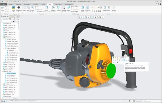
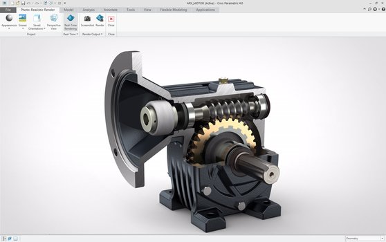
Creo Parametric 3D modeling software
Smarter design. Starting today, this is not just any product, but yours. Creo Parametric offers the basic modeling capabilities you expect from the industry leader, along with innovative additive manufacturing, model-based definition, and intelligent, connected design capabilities. Optimized workflows and an intuitive user interface complete the picture.
Creo Parametric will meet your every need.
Creo Layout: 2D CAD software
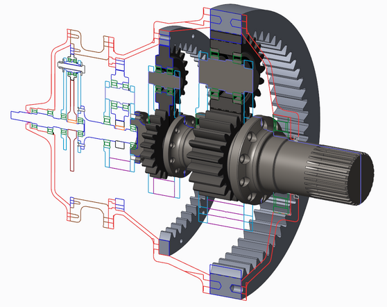
Creo Layout is an intuitive 2D CAD application that allows the project team to create detailed 2D concepts, complete with information such as Creo Layout2quote and annotations.
You can then produce equally detailed 3D models from the same 2D data without having to change CAD systems or pass 2D data to 3D CAD experts. Instead, you can leverage 2D data to produce perfect 3D models that accurately reflect the original design intent. And thanks to process automation, you can be sure that the final CAD results will be updated regularly and transparently
Size and annotate your 3D models with Creo's Model-Based Definition
Enhance collaboration across your organization with a single source of data for engineering design, manufacturing, quality, and your supplier base.
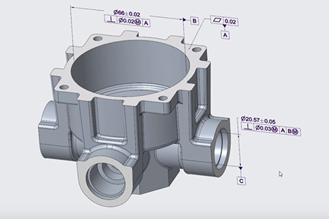
What is the Model-Based Definition (MBD)?
Model-Based Definition is an approach to create 3D models that actually contain all the data needed to define a product. With the MBD, the model becomes the reference source for all technical design activities. This model can then be used downstream, by suppliers, and in all organizations of a company.
Design in a multi-CAD environment
Creo is excellent in multi-CAD environments, enabling you to enhance design collaboration or consolidate your company's CAD applications.
Few manufacturing companies have the privilege of working in a homogeneous CAD environment. Within their firewalls, they use an average of 2.7 CAD systems. Beyond those firewalls, though, there are customers to impress, supply chain dynamics to respect, and existing systems that contain outdated projects. The sticking point is that each company uses a different CAD system. And the proliferation of systems produces inefficiencies and redundancies: data must be recreated, conversion problems emerge, and design intentions are easily lost. You might think that working with multiple systems is inevitable. Some members of your design supply chain probably have a habit of creating files in a format other than your preferred system. For product developers, this results in wasted time and more errors when exchanging and thus correcting or re-creating models between suppliers and supply chain partners.
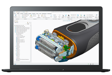
Thermal analysis
The term thermal analysis refers to a group of techniques for analyzing the ways in which the physical properties of materials change as temperatures change. It is easy to see how such analysis is essential for aeronautics, medical devices or consumer electronics. However, a thermal analysis of some kind is required for most products.
CAM software
Increase productivity with more efficient machining and toolpath design
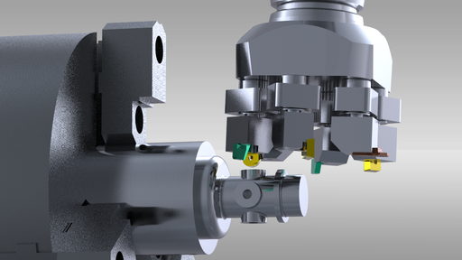
CAM software and plastic parts
CAM software can also be particularly useful in the design and manufacture of molds for plastic parts. Once the mold is designed, it is essential that the mold core and cavity, sliders and cooling channels are efficiently machined with absolute precision. CAM software allows you to design the optimal toolpaths for this purpose.
Don't waste time grouping the various components of an integrated workflow for precise part machining. Creo's tooling and NC solutions offer a comprehensive set of features to achieve the highest levels of quality and accuracy in the shortest time.
System Requirements
* Intel® Pentium® 4 or AMD Athlon® 64 processor
* Intel Pentium 4 or AMD Athlon 64
Intel Pentium (4, M, D)
-Intel Xeon
-Intel Celeron
-Intel Core
-AMD Athlon
-AMD Opteron
Note: Single, dual and quad-core processors are supported.
*Operating system:
Windows 7 32 and 64-bit editions of Ultimate, Enterprise and Home Premium
Windows 8: 32 and 64-bit editions of Windows 8, Windows 8 Pro, Windows 8 Enterprise
Windows 8.1: 32 and 64-bit editions of Windows 8.1, Windows 8.1 Pro, Windows 8.1
Enterprise
Windows 10 64 Bit
* Minimum Ram: 512 Mb
* 3D Video Display compatible graphics card with OpenGL support
Installation procedure
1. From the "PTC Creo v7.0.2.0 [64 Bit]" folder and from the "crack" and "License Windows" subfolders, start the "FillLicense" file, the "PTC_D_SSQ.dat" file will be generated which will be copied where you he wants to remember the path where he is.

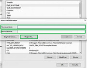
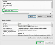
2. Move to Control Panel -> System and Security -> System, select "Advanced System Settings". Choose "Environment Variables"
"User variables for (Your nickname)", click on: New and enter:
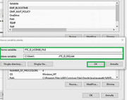
Variable name: PTC_D_LICENSE_FILE
Variable value: "Browse file" and select the license: PTC_D_SSQ.dat created previously and confirm.


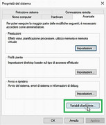
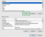
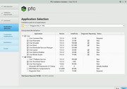
3. Mount the PTC.Creo.7.0.2.0.Win64.iso image, and start "Setup.exe". Select "Install New Software", click on Next, accept the terms, tick "By checking this box, I confirm that software ..." then continue with Next, and check that the file is present in "License Summary" "PTC_D_SSQ.dat" -> Available. Leave all the items selected, Next button and then press "Install"


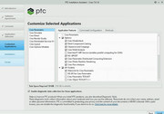
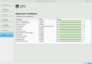
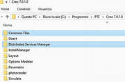
4. Once the installation is complete, move to the "Crack" folder and from "Creo 7.0.2.0" copy the "Common Files" and "Distributed Services Manager" folders and paste them into This Pc: Local drive C: -> Programs -> PTC -> Creo 7.0.2.0

5. Start the SolidSQUADLoaderEnabler file, confirm and restart the operating system.


6. Lock the products in your Firewall
*Installation Procedure, Illustration, Screenshots and Test by JackieALF
|

